While the operation of the Power Fault Analyzer is relatively simple, there are some points that will help in getting accurate results.
Experience has shown that actual cable routes and cabinet locations do not always agree with the documented cable plant maps. When you are working with a cable that is experiencing difficulty, it is useful to have a copy of the plant map plus have some first-hand knowledge of the actual cable plant routes.
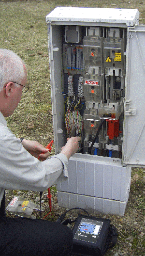
When deploying the instruments it is extremely important to connect the instrument’s test leads between neutral and a power phase and never connect from phase to phase.
Sometimes the phase conductors’ color coding is not consistent from cabinet to cabinet. If the instruments are not indicating communications, this may be due to midlabeling of phase color coding. If no communications, try moving one of the instrument's red probe connection to another phase.
Getting a distance to fault reading will only be as accurate as the total cable length distance you enter in the Power Fault Analyzer’s Display mode. Be sure to check the actual route of the cable, then measure the route from cabinet to cabinet. Remember to include the instruments' probe lengths and the cable depth (for each cabinet, down one cabinet and up another).
Once you have determined the distance to the fault, look around the area for a likely point of cable damage. For example, if the distance to fault reading directs you to a location within a few meters of a streetlight or a customer drop connection, then you might suspect that connection splice as the culprit rather than the actual distance the instrument gave you. Distances that are not exact may be due to incorrect total cable lengths or routes.
For additional information please contact us.
|